For the Spring Assemblage Shown in Figure
Node 3 displaces an amount. Determine the reactions at the fixed nodes 1 and 5.

Solved For The Spring Assemblage Shown In Figure P2 2 Chegg Com
Let k1 1 kip in k2 2 kip in k3 3 kip in k4 4 kipin and k5 5 kipinFigure.
. Node 3 displaces an amount Î 1 in. Node 3 displaces an amount Î 1 in. Use the direct stiffness method for problem.
For the spring assemblage shown in Figure P2-5 obtain the global stiffness matrix by the direct stiffness method. For the spring assemblage shown in Figure P2-5 obtain the global stiffness matrix by the direct stiffness method. Node 3 displaces an amount δ 1 in.
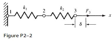
For the spring assemblage shown in Figure P22 determine the displacement at node 2 and the forces in each spring element. For the spring assemblage shown in Figure 213 obtain a the global stiffness matrix b the displacements of nodes 24 c the global nodal forces and d the local element forces. For the spring assemblage shown in Figure P22 determine the displacement at node 2 and the forces in each spring element.
Also determine the force F 3. Node 3 displaces an amount d 1 in. In the positive x direction because of the force F 3 and k 1 k 2 500 lbin.
The strain energy of the system is 82816 J If the work done by the external force is computed assuming the force had remained constant from the initial state to the final state we obtain Mechanical work of the applied force f 4x u 4xf 4y u 4y2x82816 J. 1 Answer to For the spring assemblage shown in Figure P22 determine the displacement at node 2 and the forces in each spring element. For the spring assemblages shown in Figure P2-12 determine the nodal displacements the forces in each element and the reactions.
In the positive x direction because of the force F 3 and k 1 k 2 500 lbin. For the spring assemblage shown in Figure P2-5 obtain the global stiffness. 300 200 500 m 300 1000 N I 400 2 4 Figure la b The nonlinear spring in Figure 1b has the forcedeformation relationship f k8².
Get solutions Get solutions done loading. Also determine the force F3. For the spring assemblage shown in Figure P2-2 determine the displacement at node 2 and the forces in each spring element.
For the spring assemblage shown in Figure P2-5 obtain the global stiffness matrix by the direct stiffness method. For the assemblage shown in the figure which of the following is correct about the displacement of node 3. The spring constants are all equal to k ¼ 200 kNm.
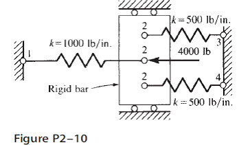
For the spring assemblages shown in Figure P2-15 determine the nodal displacements the forces in each element and the reactions. Assume the rigid vertical bars at nodes 2 and 3 connecting the springs remain horizontal at all times but are free to slide or displace left or right. Let k1 1 kip in k2 2 kip in k3 3 kip in k4 4 kipin and k5 5 kipin.
In the positive x direction because of the force F3 and k1 k2 1000 lbinFigure. For the five-spring assemblage shown in Figure P2-17 determine the displacements at. Solutions for Chapter 2 Problem 10P.
Also determine the force F3. For the spring assemblage shown in Figure P2â2 determine the displacement at node 2 and the forces in each spring element. Assume the rigid vertical bars at nodes 2 and 3 connecting the springs remain horizontal at all times but are free to slide or displace left or right.
Also determine the force F 3Given. For the spring assemblage shown below determine nodal displacements the forces in each element and the reactions. A First Course in the Finite Element Method 6th Edition Edit edition Solutions for Chapter 2 Problem 15P.
For the five-spring assemblage shown in Figure P2-17 determine the displacements at. Let k1 1 kip in k2 2 kip in k3 3 kip in k4 4 kipin and k5 5 kipinFigure. For the five-spring assemblage shown in Figure P217 determine the displacements at nodes 2 and 3 and the reactions at nodes 1 and 4.
Express the total potential energy of the spring and use this expression to. In the positive x direction because of the force F 3 and k 1 k 2 500 lbin. In the positive x direction because of the.
Let k1 1 kip in k2 2 kip in k3 3 kip in k4. For the spring assembly shown in Figure P13 s olve for the displacements and the reaction force at node 1 if k 1 4 k Nm k 2 6 k Nm k 3 3 k Nm F 2 30 N and F 4 50 N. Use the direct stiffness method for problemFigure P2-15.
This problem has been solved. Node 1 is fixed while node 5 is given a fixed known displacement d ¼ 200 mm. There is an applied force at node 3 of 1000 N to the right.
Use the direct stiffness method for problemFigure P2-10. For the spring assemblage shown in Figure P2-5 obtain the global stiffness matrix by the direct stiffness method. Is unkown to be found Two-spring assemblage O us fixed value Related Book For Free.
For the spring assemblages shown in Figure P2-10 determine the nodal displacements the forces in each element and the reactions. Express each of the local element stiffness matrix as follows. There is an applied force at node 3 of 1000 N to the right.
Also determine the force F 3. For the spring assemblage shown in Figure P23 obtain the global stiffness matrix by direct superposition. For the spring assemblage shown in Figure P2-5 obtain the.
The strain energy for the spring is 2 3 2 4 1 G ku y31250 J. If nodes 1 and 5 are fixed and a force P is applied at node 3 determine the nodal displacements. For the five-spring assemblage shown in Figure P2- 17 determine the displacements at nodes 2 and 3 and the reactions at nodes 1 and 4.
A For the spring assemblages shown in Figure 1a use the principle of minimum potential energy to determine the nodal displacements and the forces in each spring. Access to 2.
Solved For The Spring Assemblage Shown In Figure P2 2 Determine Chegg Com
Solved For The Spring Assemblages Shown In Figure Determine The Chegg Com

For The Spring Assemblage Shown In The Figure Above Determine The Displacement At Node 2 And Youtube
0 Response to "For the Spring Assemblage Shown in Figure"
Post a Comment